Lifecycle Mapping - Understanding and Designing PLM - shown by a practical example of requirements management
1. why information development must be designed in the PEP
The design of lean production systems and optimization of global supply chains to increase productivity is at the core of every corporate strategy today. The focus of optimization is increasingly turning to the product creation process, as the realization grows that its appropriate design is a central prerequisite for continuing to operate successfully on the market in the future.
Due to the drastic changes in product development, this is currently becoming more and more urgent. On the one hand, products are becoming more complex due to the integration of intelligent components and the increasing number of variants, and on the other hand, the number of activities to be carried out simultaneously in product development is increasing due to the shifting forward of tasks. Many of the activities that take place today in early development phases were carried out a few years ago later in development with physical prototypes. Where models used to be created using drawings on paper, today models are modeled in IT applications (e.g. CAx, digital factory, systems engineering, etc.). Currently, we are experiencing an almost explosive increase in the number of model-based applications used in PDP (see Figure 1).
Since all models created in the PDP are abstractions of the products to be developed, they have multiple redundancies. Because models are often created simultaneously over the course of the PDP, interactions arise between the models so that their information must be continuously reconciled.
Most players in the PEP are not aware of this. Often - when the resulting problems become too big - there is a call for new, even more powerful models, which then have to be handled additionally. As a result, the PEP becomes even more complex.
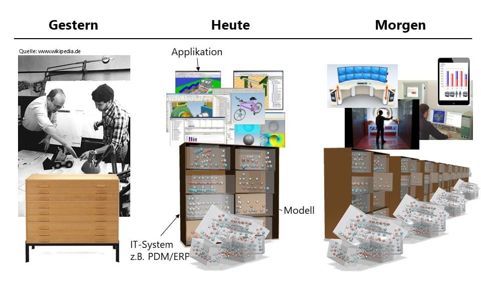
Figure 1: The model explosion in the product development processThe current situation around PEP and PLM is comparable to the discussion in production management at the beginning of the 80's of the last century. Automation had become widely accepted. On this basis, the discussion about lean management could then develop. After many routine processes of the PEP have been successfully automated today through the successful introduction of PLM components, the conviction is also growing in the PLM discussion that a consistent design of the information development in the PEP will be a next step to the success of PLM.
2. the idea of lifecycle mapping
Lifecycle Mapping took its origin in discussions of experienced PLM solution architects. The use cases they looked at from various industries and companies showed that the operational interaction of product information had not been discussed in the past. For this reason, essential aspects are often not considered when planning PLM projects. This sometimes jeopardizes PLM projects because the common understanding of the supplier, the project team and the end users is not created.
Lifecycle Mapping makes it possible to analyze the operational information development in the PEP. The focus of the modeling is on the models of the PEP that actually live in the IT systems. To make modeling easy, Lifecycle Mapping relies on IT-neutral symbolism that is related to the mindset of value stream design.
Lifecycle maps (LIF maps) can be used to display maps of the PDP. These serve as a central communication and optimization tool in PLM projects and contribute significantly to "talking about the same thing".
3. create lifecycle maps
In the application, LIF maps are created of the current state and one or more future states to be developed. In PLM projects, it has proven suitable to develop the LIF map of the Current State together with all participants at the start of the project and to take the time to discuss it in detail. This creates a common understanding of what is happening in the PDP. In a further discussion, areas with potential for optimization can be drawn in the Current State LIF map. Once this is done, possible optimization scenarios are developed using Future States LIF maps.

Figure 2: Lifecycle map of a simple current stateThe procedure for lifecycle mapping is explained below using the example of a simple current state (Figure 2). The basis of the lifecycle map is the time axis. The milestones of the PDP that are essential for the observation are noted on it. In the next step, the living submodels are drawn into the LIF map as rectangles. Here it makes sense to concentrate on submodels of a product or a product family. The rectangles start at the time they are first initiated in the PEP. Their length across the timeline symbolizes their development over time. Strictly speaking, a submodel does not end because the data is retained beyond the product development process and even "finished" submodels are often modified at a later point in time. The rectangle in the lifecycle map therefore ends at the point in time when the work on the partial model is essentially complete. If it is necessary to represent the "continuing life" aspect, a smaller filled rectangle and/or a line continuing across the timeline is used. The smaller width represents the lower intensity of work on the sub-model (Figure 2, representation of modeling intensity). When analyzing LIF maps, it is important to define a focus in advance and stick to it. If the technical discussions nevertheless threaten to go beyond this focus, this can be prevented with the "out of scope cloud" (Figure 2). It can be used to record aspects outside the focus in the LIF map. In this way, it is always clear in the discussion that this area exists, but that it is not discussed in the map that is currently being created.
When analyzing the PEP with the help of submodels, two essential aspects of observation arise, on the one hand the development of the submodel itself (i.e. what happens within the drawn rectangles) and on the other hand the interaction between the submodels over the time course of the PEP. LIF maps show the second aspect, the interaction between submodels. The first aspect is investigated using other Do(PLM)Con diagrams and is not the subject of this article. To represent the interaction of submodels, the LIF map uses different connecting lines (lines, arrows, dashed arrows, etc.) and transition symbols assigned to them. The connecting lines describe how the information is related or set to each other (Figure 2, linkage vs. derivation). The transition symbolism shows how the linkage is organized. For example, the transition symbols shown in Figure 2 mean that the link between the models is maintained by a responsible person and that semantic integration of the data is performed at that point. How exactly this is done can be analyzed in detail e.g. with the help of the PLM-ML Semantic Map. For further symbols, please refer to the example described below.
4. delimitation of submodels
An important aspect of lifecycle mapping is the identification and appropriate delineation of the relevant submodels. This is considered in more detail below. In LIF maps, the living submodels relevant for the observation, i.e., specifically submodel instances, are drawn in. One submodel instance is e.g. the product structure with geometric CAD data of product A (see Figure 3, the submodel instance geometric model product A), another would be e.g. that of product B. For the instance there is, as in computer science, the submodel type, i.e. "product structure with CAD data". It should be noted that the terms instance and type cannot be used for submodels of the PEP with the uniqueness that is usual in computer science.
The delineation of submodels is similar to the delineation of suboperations in assembly. A sub-operation is formed in a granularity that is sufficient for the analysis case. If in the course of planning the necessity is recognized to delimit the sub-operation more finely granular, this can be done without any problems. Planning starts, for example, with the sub-operation fastening screws. If necessary, this can be detailed to the sub-operations pick up screw, pick up wrench, apply wrench, etc.
The procedure for delimiting submodels is analogous. In the first step of an analysis, the product structures living in the existing IT systems can be assumed as submodels (Fig. 3, the three models on the left). If it becomes apparent during modeling that a structure assumed to be a submodel contains several relevant submodels that should be considered separately, a separate rectangle can be modeled in the LIF map for each one.

Figure 3: Delimitation of submodelsFor understanding, some concrete examples: So-called baselines are often derived from product structures over the time course of the PDP. A baseline freezes a temporal state of the structure. Depending on the modeling case, the baseline can be seen as an integrated part of the "product structure" submodel or as a separate "baseline" submodel. A second example is variant options. These are often maintained in IT systems on logistical product structures. This gives the impression that a "product structure incl. variant options" submodel exists. However, this is not the case. From a total set of possible options, the product structure instance contains the valid ones in its context. Therefore, a submodel "Total set of options" must exist. The options contained in the product structure are therefore extracted from the "total set" submodel as a subset and are then introduced into the product structure, for example, as a copy or link.
The delimitation of submodels sounds difficult in the theoretical description. However, practical experience shows that the delimitation can be carried out easily, almost intuitively. This is because the submodels are abstractions of what those involved in the PDP work with on a daily basis. The guideline mentioned in Figure 3 is helpful for the delimitation: The information in a submodel is coherent in terms of content, has a strong connectivity and has a similar time behavior.
5. creation of a lifecycle map for requirements management
The following is an example of a LIF map for the use case "exchange of specifications" (see Figure 4, detail A-F). This use case often takes place between OEM and Tier 1 supplier. Shown is the planned future state. The OEM's requirements (Figure 4) are handed over by the OEM to the Tier 1 Supplier (Figure 4, Detail A). The handover takes place via an electronic document and is handled manually mostly via e-mail with advance notice by telephone. This is the OEM's requirement. How the OEM manages its requirements internally is not relevant for consideration and is therefore marked with the out of scope cloud. In order to be able to manage the requirements in their current state, they are entered and managed in a separate submodel at the tier 1 supplier (Figure 4, Customer requirements). This involves a transformation of the electronic document into the format of the data management system used by the supplier, which is handled by an employee (Fig. 4, Detail A transition symbol). The customer requirements are now evaluated by the Tier 1 Supplier. The assessment is done in a separate model that evolves in parallel over time and is linked to the customer requirements model (Figure 4, Annotated Customer Requirements). It contains the Tier 1 Supplier's assessment and comments on the OEM's customer requirements. It also checks whether customer requirements have already been met by other products from the supplier's portfolio. For this purpose, the commented customer requirements are linked with internally defined requirements of comparable products of the supplier in order to identify the requirements for which solutions are already available (Fig. 4, detail B).
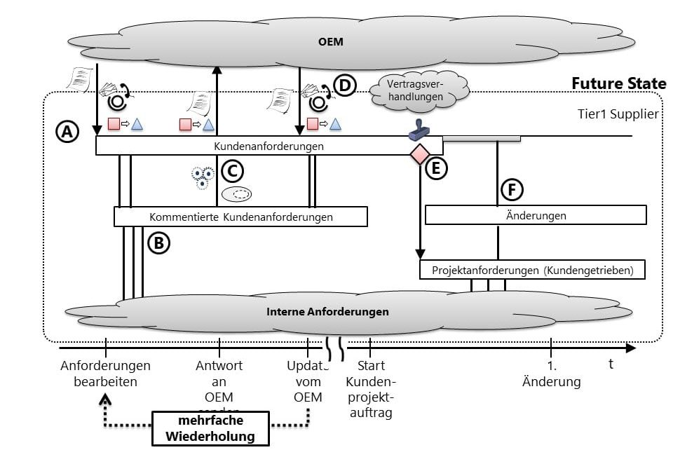
Figure 4: The lifecycle maps of the use case "exchange of specifications
At previously determined times, subsets of the commented customer requirements are fed back to the OEM (Figure 4, event on timeline "Send response to OEM"). The symbolism can be read as follows (Figure 4, Symbols at arrow in detail C): The "subset symbol" represents the selection of a subset of the requests to be routed out. The "gear symbol" indicates that this is done automatically by the IT system. The "square to triangle" symbol represents a conversion of the data, and the "written paper" symbol defines that it is a standard readable format. The OEM takes the comments, adjusts its requirements if necessary, and sends back these adjusted requirements as well as any new requirements that may have arisen (Fig. 4, detail D). The procedure is analogous to the initial transfer of the requirements. The process described above is repeated several times until the requirements discussions have reached a level of maturity at which they can be released and coordinated requirements are thus available.
Once this is done, contract negotiations can be conducted. These are merely noted in the LIF map. If these lead to a customer project order, the agreed requirements are released and assigned a release status (Figure 4, Detail E). The requirements are subsequently transferred to the Project Requirements model, which contains the requirements that are valid for the project. This is where change management comes in. This is handled by a submodel in which all changes are recorded. If the OEM makes changes to the requirements, these are incorporated into the project by means of a formal change request. The changes and their effects are recorded in detail in the change model and linked to the requirements affected by the change in the requirements model.
6 Conclusion and outlook
LIF maps provide a simple language that makes it possible for the first time to discuss operational information development in the PEP. All persons involved in the PDP can understand this language with a little practice without special IT knowledge. With LIF maps, organizational aspects and specific lifecycle behavior can be formulated even before a PLM introduction, which in conventional PLM introductions only become apparent during the ramp-up of the already introduced PLM system. This makes it possible to conduct a genuine optimization discussion with both the executing specialist departments, the IT departments and the system provider.
The example shown is a concept of a Future State that the company in question wants to implement by means of a PLM system. For the implementation, the Do(PLM)Con provides further maps that enable the transition from the LIF map to a detailed IT concept.
Source
- Fischer, Jörg W.; Rebel, Martin; Lammel, Bernhard; Gruber, Jürgen: Systematic Optimization of the Product Development Process with PLM-ML. In: ProduktDatenJournal, Darmstadt, 19(2013)1, pp.58-62.
- Fischer, Jörg W.; Lammel, Bernhard; Hosenfeld, Dirk; Bawachkar, Deodatt; Brinkmeier, Bernd: Do(PLM)Con: An Instrument for Systematic Design of Integrated PLM Architectures. In: Smart Product Engineering. Eds: Abramovci, Michael; Stark, Rainer. Heidelberg: Springer 2013. pp. 211-220 (Lecture Notes in Production Engineering, Volume 5.).
- Fischer, J.W., Brinkmeier, B.: Do(PLM)Con - Proposal of a taxonomy for the development of PLM-Architectures. In: ProductDataJournal, (2012)1, pp. 24-28.