Recognize patterns where others see chaos
The product development process comes into the optimization focus
Optimization and operational design of production are taken for granted today. However, engineering in the product development process (PDP) was excluded from optimization for a long time due to its complexity. This has changed little even with the discussion about Product Lifecycle Management (PLM). In the current discussion, PLM is often limited to an IT topic. Effects that arise in the operational handling of the information generated in the PDP - referred to in the following as lifecycle effects - are mostly dismissed as non-existent. Often, PLM solutions are required to resolve all of these effects, which are perceived as negative by users, by installing software. However, lifecycle effects are intrinsic components of the PDP, the penetration, understanding and appropriate handling of which are a necessary prerequisite for successful engineering. Lifecycle effects show up through patterns in lifecycle maps. Once such a pattern has been found, a suitable organizational solution for it can be designed and implemented with the support of a PLM system.
Interactions in the product life cycle
In order to understand the effects that occur in the operational handling between the information generated in the PDP, it is necessary to consider today's product development. In the meantime, all essential product and production aspects are examined in advance with computer models. This means that in the day-to-day business of the PDP, a wide variety of product models are worked on simultaneously in a large number of different applications and systems. Since all these models represent aspects of the same product, they have a high degree of redundancy. As a result, findings about the product from one model influence many of the dependent models. In modular development based on the reuse of the same components in different products, the dependency problem is exacerbated.
The following analogy is helpful to visualize this. Every model that is mapped from the product in an application (be it a CAD system, simulation, Excel, PLM system, etc.) can be compared to a box containing balls. The balls in the boxes represent the model-specific information (e.g., the parts, assemblies, or components of the product). The balls within a box are explicitly structured and networked. This networking is thus visible and manageable. There are interdependencies between the balls across boxes, i.e. they are implicitly networked by "invisible" strings (see Figure 1). If you pull on a ball, then you -often unknowingly- also pull on an invisible string and influence balls in the other boxes. If only one such effect is overlooked, high costs are quickly incurred. For example, at an automotive supplier, a design change requested by the customer was adjusted in the design models, but not in the quality assurance models. Good parts were declared as rejects over several days due to outdated quality assurance documents and scrapped. The resulting damage ran into millions. Such cases are rarely documented. If it can be avoided, they also do not reach the management in their own company.
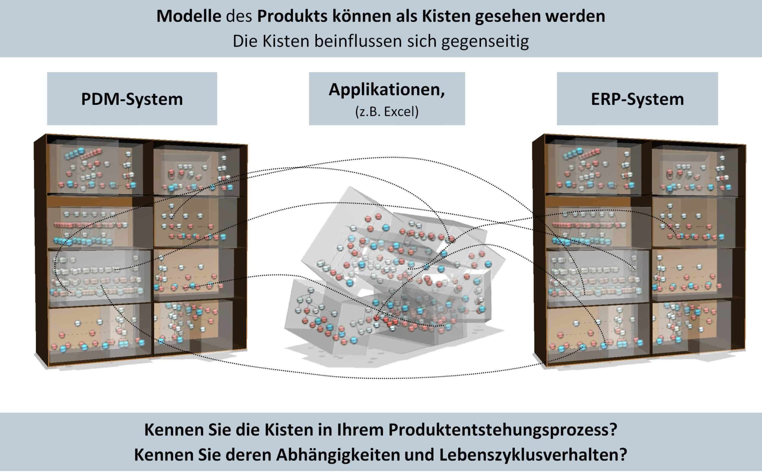
Figure 1: The analogy of boxes connected by invisible strings
Understanding life cycle effects and dealing with them in an organizationally appropriate way is therefore a high priority. However, most players in the PDP are not aware of them. Often - when the problems become too big - there is a call for new, even more powerful software models, which then have to be handled additionally and ultimately exacerbate the problem. Up to now, the effects of lifecycle effects have generally not been recognized in PLM projects and are therefore often not taken into account. The reason for this is the preparation of PLM systems in test environments of the IT departments. Operational work is not carried out on the test data available there. Consequently, the lifecycle aspects do not occur there either.
Lifecycle Mapping
The lifecycle mapping of the Do(PLM)Con method [1,2] can be used to create maps of the time-dependent information flow between the models of the PDP. With its help, patterns of recurring lifecycle effects can be localized, understood and designed according to individual company requirements. It can often be determined that comparable behavior within the life cycle occurs in different domains.
Recognizing patterns where others see chaos - examples of life cycle effects
Figure 2 shows exemplary lifecycle maps of two typical lifecycle effects (for further examples see [3]). Lifecycle effect 1, concurrent progression, describes the case of a successor scope based on the information derived from a predecessor scope. This results in two parallel life cycles with very similar or congruent information at the beginning, which become more and more separated from each other over time. Concurrent evolution is well illustrated by the example of product structures (Fig. 2, detail 1). Product 0814 is the predecessor of product 0815. Product structure 0815 is derived from the structure of product 0814. Both share common assemblies. However, the consistency of these common assemblies decreases over time due to product-specific adjustments. The more time passes and the stronger the impact of product-specific adjustments, the more difficult it becomes to keep the changes consistent in the separated life cycles. In the example described, the improvements to the predecessor product 0814, for example, which were triggered by feedback from the service, can only be transferred to the product structure 0815 with additional effort.
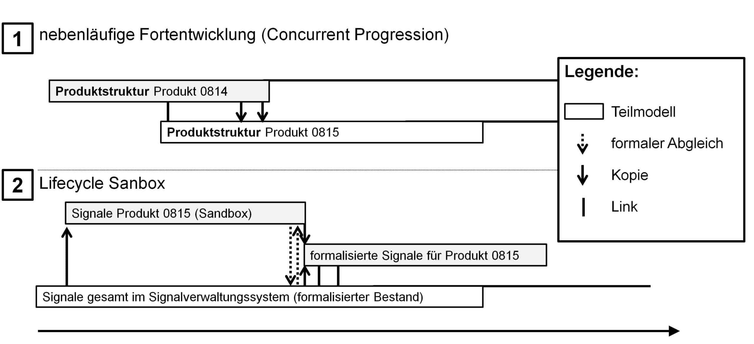
Figure 2: Examples of life cycle effects
Lifecycle effect 2, the lifecycle sandbox, describes the case in which a volume of information is created in a decoupled planning area and, after reaching a certain level of maturity, must be integrated into a formalized inventory or reconciled with an existing inventory. Lifecycle sanboxes are a typical lifecycle effect in PDP, as they arise by themselves when stand-alone solutions are used. A simple example of lifecycle sanboxes are Excel lists that employees generate as exports from the PDM or ERP systems in order to continue working offline for a while on the basis of these lists. Such sandboxes have a high risk potential if they are not sufficiently synchronized with the valid data in the PDM system by the respective employees. In recent years, attempts have been made to avoid lifecycle sandboxes by means of a suitable PLM strategy, mostly under the motto "no redundant data storage". What often remained unrecognized was that there are necessary lifecycle sandboxes, i.e. sandboxes that are indispensable from a process perspective.
One example of a necessary sandbox (Fig. 2, detail 2) comes from vehicle electronics. ECUs communicate with the help of signals via the CAN bus of a vehicle. To prevent the risk of duplicate use of signal IDs in the vehicle, automotive companies need a signal management system, i.e., a database of valid signals and a formal application process for a signal ID.
In the early phase of the PDP, it must be possible to plan the electronics quickly. Accordingly, it is necessary for the planner to be able to create signals ad hoc without formal hurdles. The use of a lifecycle sandbox is suitable for this case. At the beginning of the work, the planner fills the sandbox with signals from the signal database that are known to him. New signals can be freely defined by the planner in the sandbox. When the planner's work has reached a certain level of maturity, a formal comparison of the planning data in the sandbox with the signals in the central database is performed. For each new signal created by the planner, a search is now made for a comparable, possibly already existing and thus also usable equivalent. If no matches were found, a corresponding provision is requested for the signal classified as new.
The same or similar lifecycle effects often occur in domains with different technical requirements. Provided they are recognized as similar, they can also be optimized with the same PLM solution concepts. Such a PLM solution concept consists of an organizational concept and designed data semantics. Suitable functions of a PLM system serve as the technical basis for realizing the concept.
In order to be able to actually use a successfully established PLM solution concept multiple times, it is necessary to localize the relevant places of use in the PDP for these. The localization of relevant locations of use is thus the prerequisite for being able to recognize comparable lifecycle effects in the various domains of the PDP. At this point, lifecycle maps (LIF maps) are a suitable tool. In the following, the localization of lifecycle effects is exemplified by a LIF map for the use case "requirement specification exchange" (Figure 3). It shows which of the lifecycle effects described above also occur in the requirements management domain.
The Use Case "Requirements Specification Exchange" in Requirements Management
The use case "exchange of specifications" takes place between OEM and tier 1 suppliers. In the case shown, the Tier 1 supplier is a transmission manufacturer.

Figure 3: The lifecycle maps of the use case "exchange of specifications
As part of a tender for a transmission, the OEM's requirements are transferred to the tier 1 supplier (Fig. 3, detail A). In order to be able to manage the transferred requirements in their current status, they are stored in a separate model at the tier 1 supplier (Fig. 3, transferred customer requirements). In the next step, the customer requirements are evaluated by the tier 1 supplier. The evaluation is documented in a separate model that evolves in parallel over time. The requirements in the two models are linked accordingly (Fig. 3, detail B). An evaluation is performed based on the database of already fulfilled requirements of similar transmissions. The relevant requirements are selected and transferred to the model of the evaluated customer requirements (Fig. 3, detail C). In the course of the request, modified requirements of the OEM are regularly transferred to the Tier 1 supplier (shown in Fig. 3, detail D). Once all requirements have been evaluated, they are returned to the OEM (Fig. 3, detail E). Subsequently, contract negotiations take place. If these are successful, the OEM and Tier 1 supplier define the valid requirements for the project, which result from a comparison of the evaluated requirements with the OEM's requirements (Fig. 3, detail F). The valid project requirements are subject to formal change management from this point on (not noted in Figure 3).
Localization of life cycle effects in the use case "exchange of specifications
In the lifecycle map discussed (Figure 3), patterns can be seen that are similar to the lifecycle effects shown in Figure 2.
The exchange of the requirements specification between OEM and supplier is similar to Cuncurrent Progression. The OEM's requirements evolve in two separate but synchronized life cycles compared to the evaluated requirements. This corresponds to a concurrent progression. However, this also requires an adjustment related to the context (e.g., reference between two different but similar products). If this is not the case, there is no sufficient match.

Figure 4: The lifecycle effects in the use case "specification exchange
The pattern that emerges between the dataset of already fulfilled requirements, evaluated requirements and handed over customer requirements is more interesting. This is a necessary lifecycle sandbox. In figure 4 this becomes still more clear by the summarized representation of the customer requirement models. The fulfilled requirements dataset is the formalized dataset. The transferred requirements and their evaluation are managed in the sandbox. The sandbox is initialized with comparable, already fulfilled requirements. From this point on, work is done in the sandbox. The requirements can now be changed without any problems and without affecting the formalized inventory. Once the requirements for the project have been defined (Fig. 4, valid requirements in the project), the sandbox can be compared with the formalized inventory. Three cases can be distinguished. In the first case, the sandbox requirement corresponds to a requirement that has already been fulfilled. In the second case, it is a new requirement. As soon as it has been solved, it can be transferred to the formalized inventory. In the third case, the requirement is similar to an existing requirement but not the same. Accordingly, a decision must be made as to whether the extension of a requirement already in the inventory is sufficient or whether a new one should be created.
Conclusion and outlook
The example explained above shows that life cycle effects occur similarly in different use cases and domains. If a localization of such patterns in different domains and application areas succeeds, two essential advantages can be derived.
On the one hand, this gives PLM-using companies the opportunity to design an organizational concept for an effect and use it multiple times. On the other hand, solution providers can offer generic PLM functionality for the known effects. These then only have to be implemented once per effect and not anew for each application and each customer.
Original source:
FISCHER, Jörg W.; Dietrich Ute:
Recognize patterns where others see chaos.
Why the "L" is often forgotten in Product Lifecycle Management
In: ProductDataJournal,
Darmstadt, 21(2014)1, pp.66-69.
(ISSN: 1436-0403)
Sources:
- FISCHER, Jörg W.; LAMMEL Bernhard; HOSENFELD Dirk; BAWACHKAR Deodatt; BRINKMEIER Bernd: Do(PLM)Con: An Instrument for Systematic Design of Integrated PLM-Architectures. In: Smart Product Engineering.ed.: ABRAMOVICI, Michael and STARK, Rainer. Heidelberg: Springer 2013. p. 211-220.
- FISCHER, Jörg W.; REBEL, Martin; LAMMEL, Bernhard; GRUBER, Jürgen: Systematic optimization of the Product Development Process with PLM-ML. In: ProductDataJournal, Darmstadt, 19(2013)1, pp.48-52.
- FISCHER, Jörg W.; STOWASSER, Sascha: Industrial Engineering and Lean Product Development. In: Industrial Engineering, Fachzeitschrift des REFA-Bundesverbandes, Darmstadt, 66(2013)2, pp.20-27.